Battery Powered PIR IR Illuminator

I've spent some time searching for an additional IR illuminator to supplement my security cameras. For those of you not familiar with what these are, the IR lights (or near-infrared, 850nm) on your camera are what allows it to see in the dark. Most cameras have decent lights, especially for a small/enclosed area. A number of mine that are outdoors simply do not have the range I desire though.
To get that range, or to illuminate other areas, I wanted a light that was battery powered (so I didn't have to rely on physical cabling). I wanted it to only come on after dark (so I don't waste battery during the day) and when there was movement (to avoid battery waste during the night). In other words, it would have the PIR (passive infrared) detection that is present on most of our outdoor security lights. Since this is going outdoors, it should be waterproof.
The only thing that matches this description is the Brinno APL200. Unfortunately, it is no longer produced, and where I have been able to find it still in stock, it is prohibitively expensive ($100 USD range). While surfing on Amazon though, I came across something similar enough that I originally thought they may have reused the same plastic body molds, and possibly the same circuit boards. This turned out not to be the case, but it still works.
Here's a sample of what it looks like: https://www.youtube.com/watch?v=uUfV4RDKDRk - This is taking from a Ubiquiti G3 Flex with it's own IR light enabled.
IMPORTANT NOTE! When lit, the 850nm LED's will glow faintly red and not produce any visible illumination. However, they are producing a LARGE amount of invisible light that can still damage your eyes. Do not stare directly into these! Additionally, these LEDs get HOT! I take no responsibility for injury, death, or damage to physical objects.
The Needful
Here are all the tools I used.
- SainSmart Pro32 Soldering Iron
- Dremel 2200 Versa Flame
- Generic tweezers or needle nose pliers
- Rosin Paste Flux
- Phillips Screwdriver (I got mine from this set)
- Soldering helper station
And the parts you will need.
- Mr. Beams MB390, either the 300 or 400 lumen version, doesn't seem to matter. $25 - $30
- 2x per light 3.3v 850nm IR LED. $2 each, plus exorbitant shipping ($8 in my case).
I've tried to list the exact tools I used, of course for the most part anything similar will work. Whatever you use in place of the Versa Flame, make sure it isn't too hot (MAPP gas torch will melt the parts!).
Disassembly
Start by removing the back of the MB390 as though you were replacing the batteries. Around the inside rim you will find four screws.
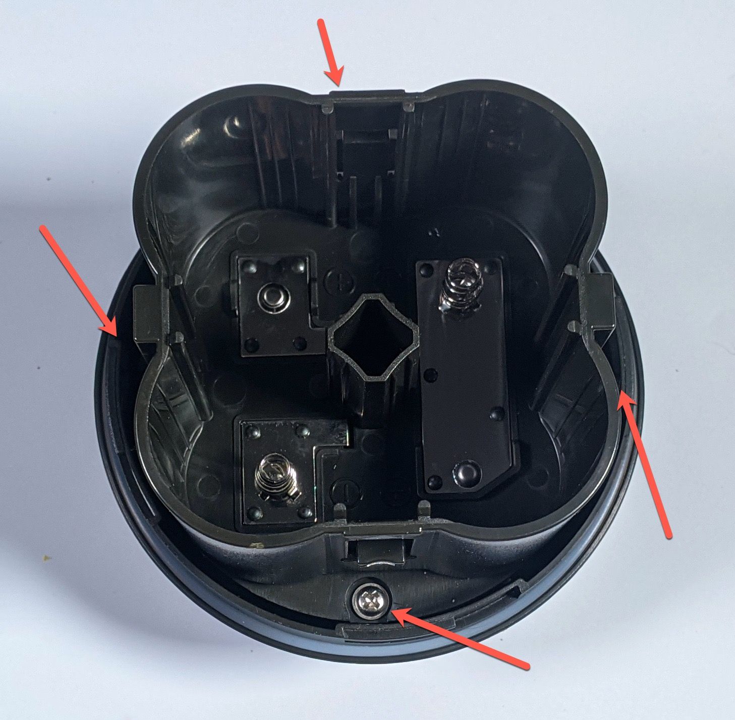
You are going to unclip the white circuit board where the top two red arrows indicate. In a few steps we'll unsolder the wiring where the bottom two arrows indicate.
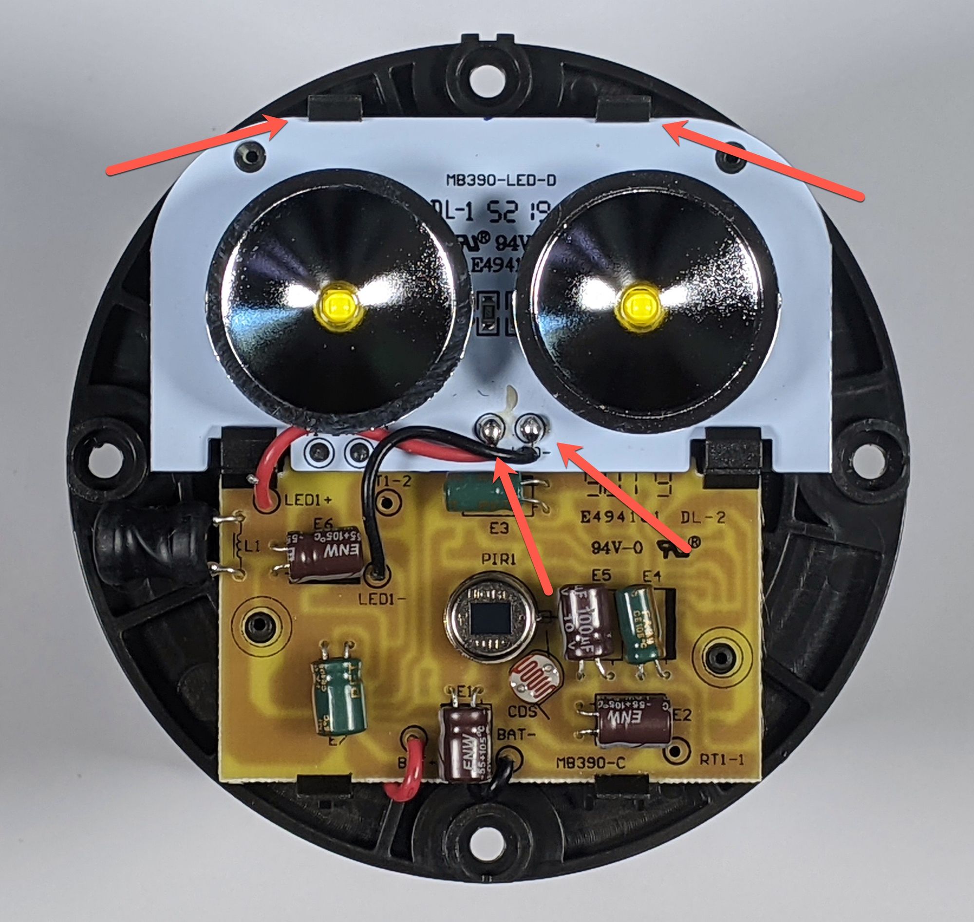
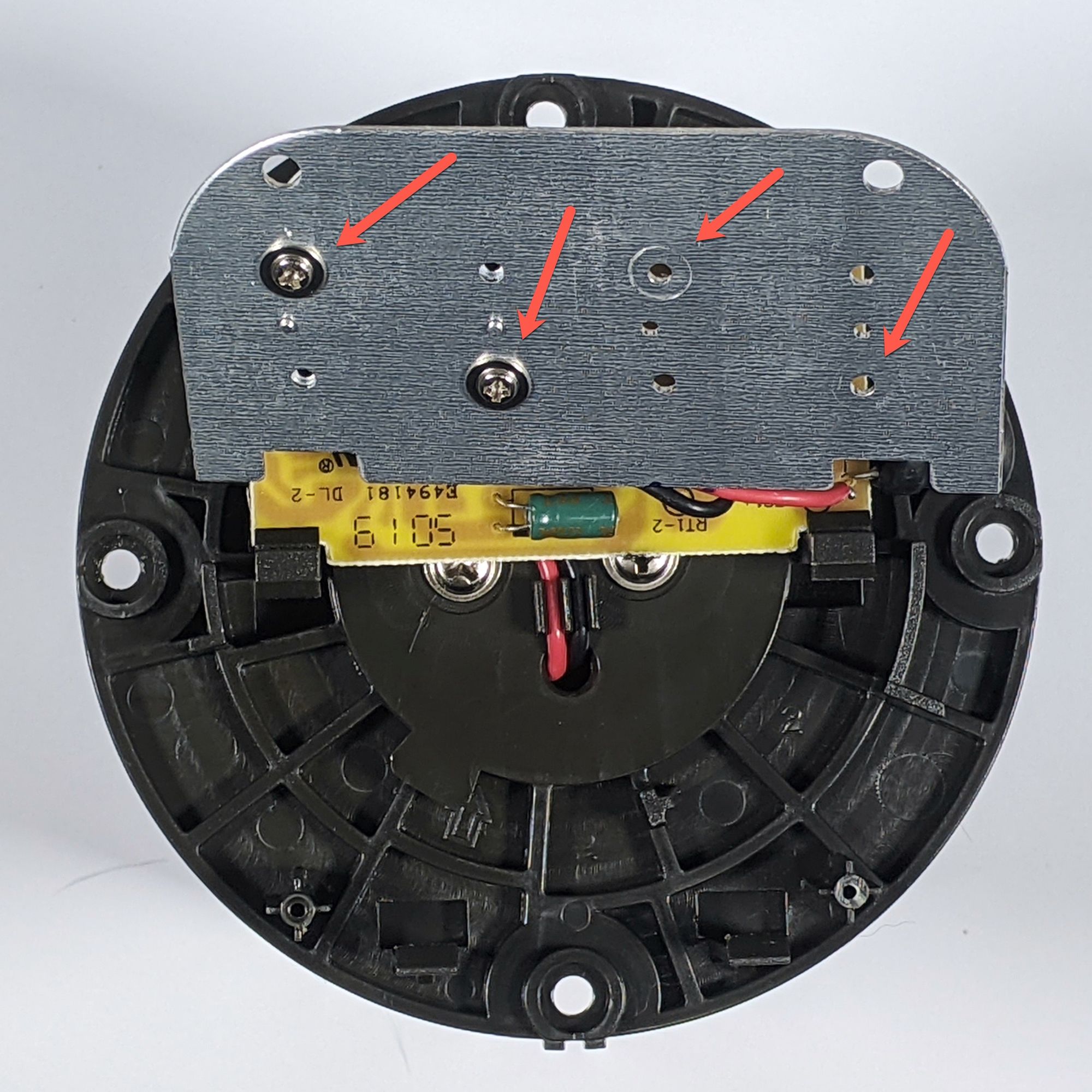
We're going to remove the reflectors surrounding the LED's by lifting up the board and removing the screws. I've removed the two of them on the right hand side already in the picture below.
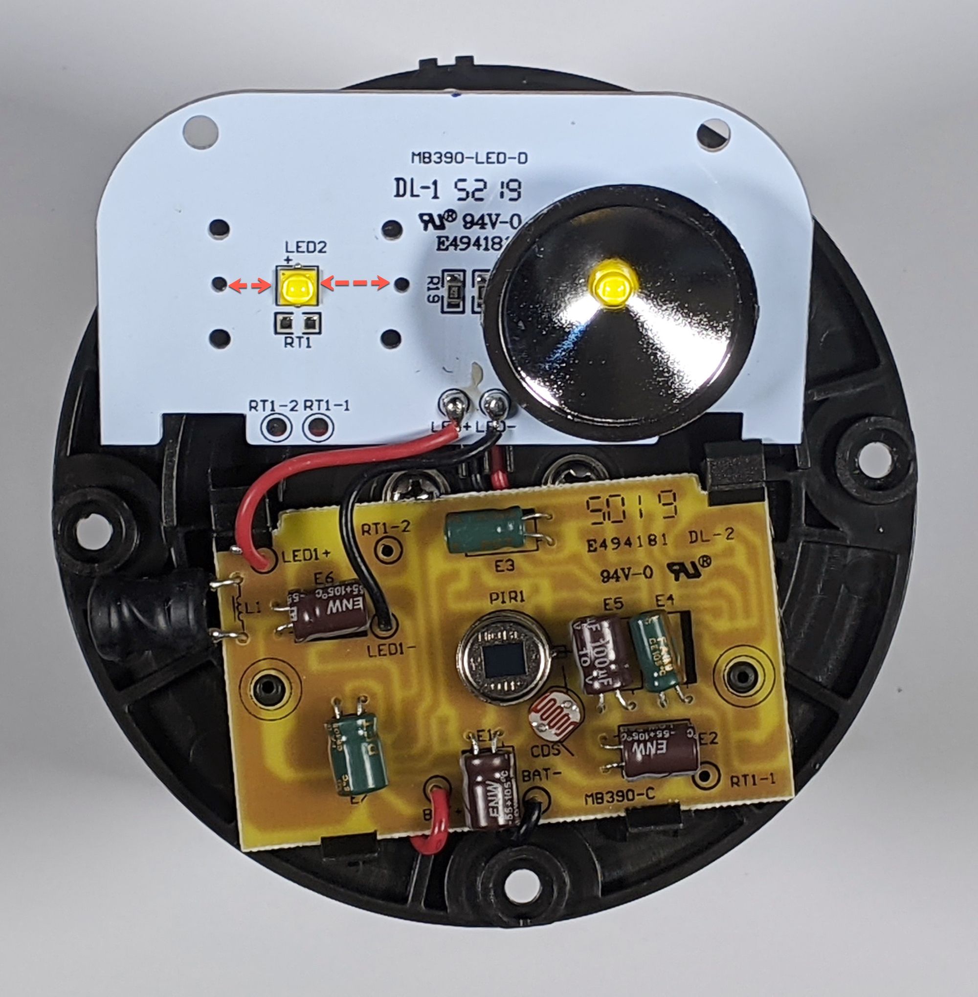
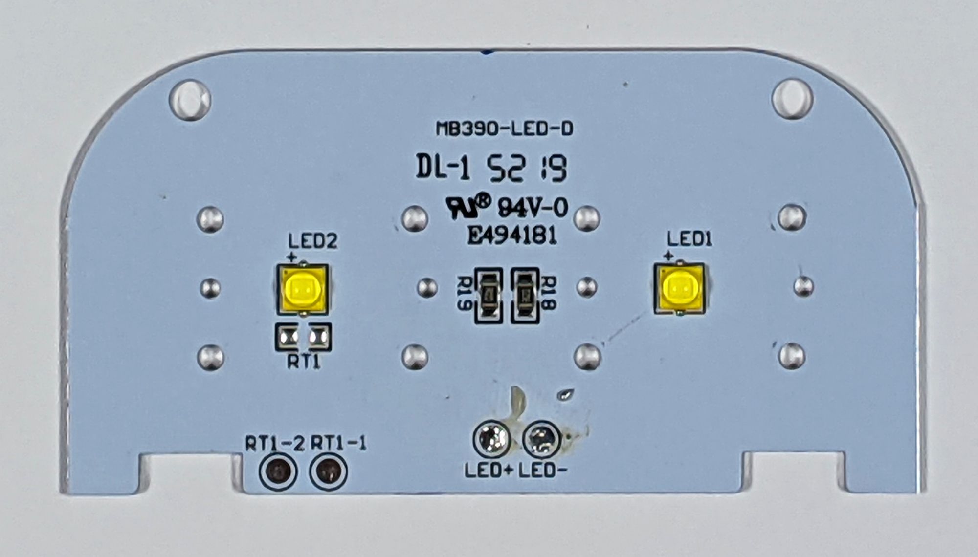
Here's the top at the same step. One thing to note when we start reassembling, the LED is not centered. When you put the reflector back on, make sure it isn't backwards.
Unsolder the wires where indicated earlier. Congrats, disassembly complete!
Remove the LED's
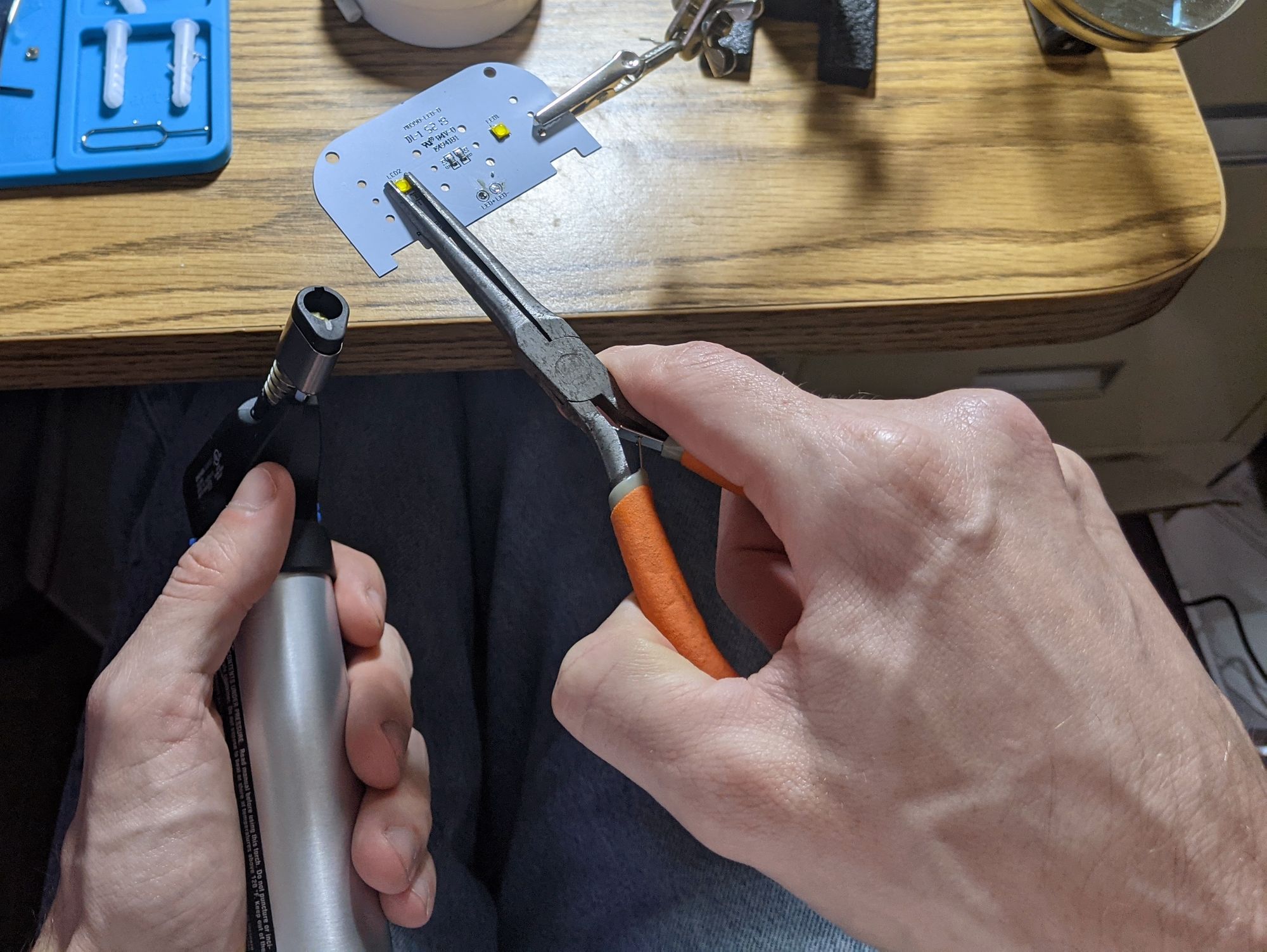
This is the fun part. We want to heat the bottom of this board, just enough loosen the LED's, not enough to damage anything. This isn't as precise as it sounds like. There are plenty of YouTube videos if you search for "desolder SMD LEDs". Here are a few different links. You can see the variety of heat sources that are used, I had a butane torch that worked well.
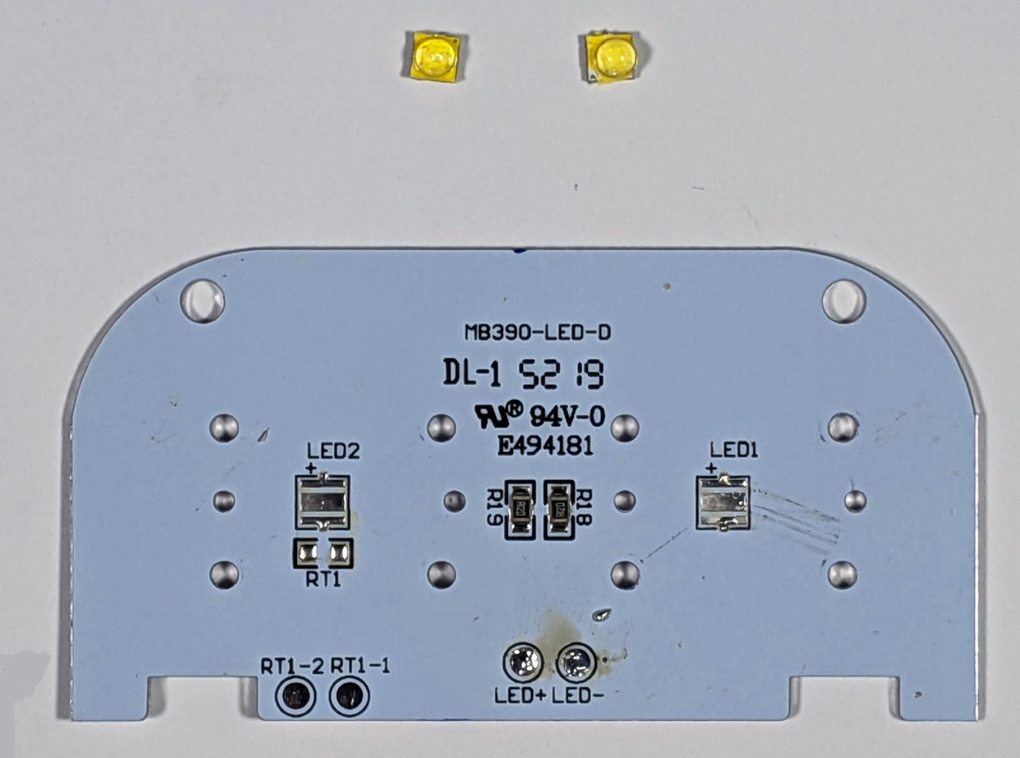
You are going to heat the bottom of this, and then gently wiggle the LED. It should slide right off with no effort at all. Don't try to hold it in your hands, it's going to get hot.
Replace the LEDs
Same process, but in reverse. Make sure you note the polarity on your LEDs! On our board we have the positive (+) at the top. Note the negative (-) side on our LED, so we want that towards the bottom.
Smear just a bit of the rosin paste flux on the pads, where you just removed the old LEDs, using a cotton swab or something similar. You might be able to get away with skipping this, but it will really help. Once you the new LEDs are in place, you can clean the excess rosin paste off with a bit of isopropyl alcohol.
You are going to heat the bottom until the solder still on the pads melts just a bit. You can see it go from a slightly matt finish to a shinny chrome look. Set the new LED on the pad and then remove the heat. It should kind of snap/slide in place if it isn't 100% perfect as the solder sticks to the contacts. Give it a few minutes to cool and then nudge it a bit to make sure it stuck.
Now reassemble the rest of the components in reverse order. Resolder the wires for the LED board, replace the LED reflectors, snap the board back in place, and the replace the front cover.
Errata
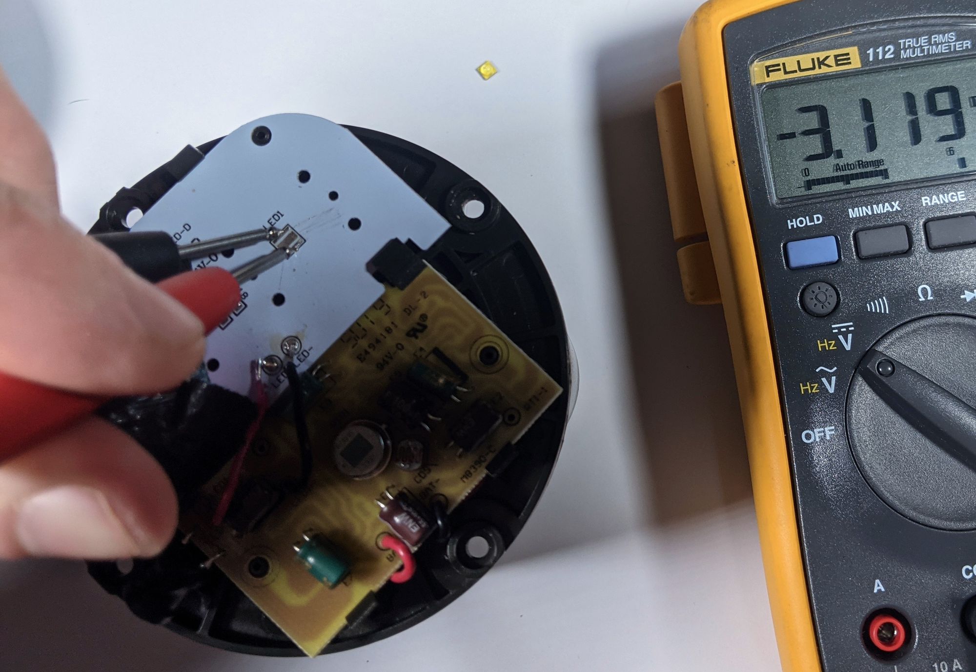
The voltage across the pads is ~ 3.1 volts, even though it's using 4x 1.5v D cells in series (for 6 volts). If you measure this with both LED's removed, you will see the 6 volts. This is split across the pads when the LED's are in place.
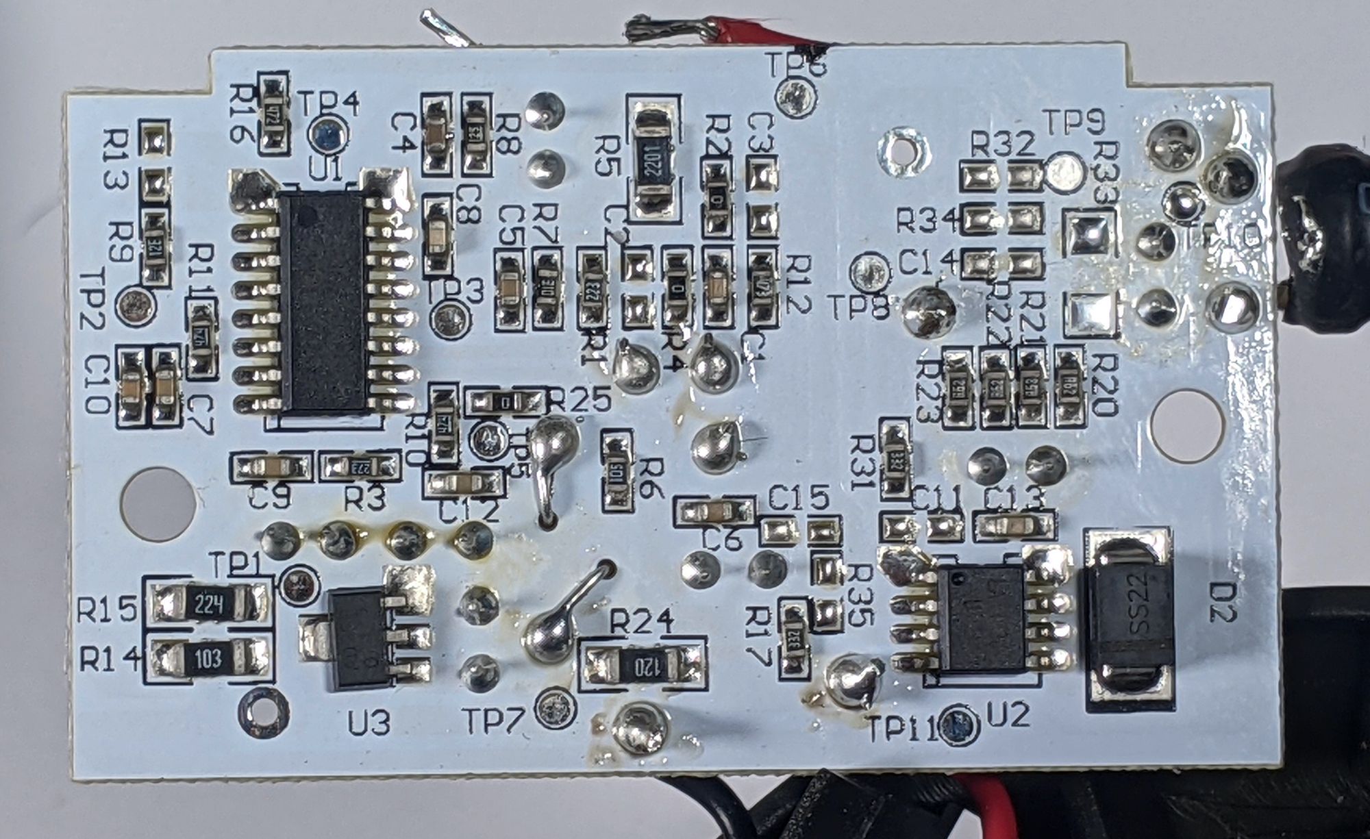
Here is the back of the bottom (yellowish) circuit board in case anyone needs it.
As I said at the top, these LEDs get very hot. I tried to measure this, and the standard LED, with a temperature gun, but couldn't get an accurate reading. So I don't know if they truly are hotter than the standard. Either way, it doesn't seem to be enough to damage the surrounding unit or cause problems, but I haven't done a large amount of testing.